Moon lander project: preliminary study of the guidance software
This article is part of a serie: Aerospace simulator
- Moon lander project: thrust vectoring with a PID controller
- Moon lander project: PID-based vs TGO-based guidance
- Moon lander project: preliminary study of the guidance software
I have always struggled during my control theory classes, and almost failed one (out of the three I attended). With this history, some people would have developed a hatred for this subject, but I personally felt in love with it: I have always found it magical to be able to control physical things with software. I love making a pile of silicon1 do things by itself, and developing control algorithms makes it possible to build robots and other automated machines.
I have been fascinated by GNC software for launchers and landers since a long time: I have made several imperfect prototypes of launcher simulators, half reverse-engineered RocketLab’s Electron’s trajectory and had a plan to write software to control my KSP spacecrafts.
More recently, a tweet has sparked my interest in Moon landers again. My current plan is to write a GNC software for a speculative Moon lander, inspired from Apollo’s LEM. I will validate the algorithm with a custom-made simulator, and later use KSP for a “real” mission. I could try to accurately follow Apollo’s control laws, but it might be too complex for a start. Additionally, they had their own constraints (for instance visibility of the landing site), which might not be relevant for me. I will start with my own custom mission and constraints and maybe later study Apollo’s trajectory in depth.
In this article, I will share my preliminary study of the architecture of the whole system. I will start with the lander’s GNC, then present the simulator, and finish with some quick study of the trajectory.
Lander’s guidance software
A descent (or ascent, or really any guidance) software is canonically made of three blocs: Guidance, Navigation and Control. In this section, I will first explain a bit what is the goal of each bloc. I will then talk about the data structures, to specify the data flow and interfaces, two critical steps to ensure a successful development and integration. Finally, I will quickly talk about some more technical points: I/O adapters and implementation.
GNC
Guidance, navigation, and control comprises of three distinct blocs, each with its own goal.

Navigation
Navigation reads the inputs from the sensors and determines the state vector: position, velocity, acceleration ; both in translation and rotation. Navigation can contain low-pass filters to remove noise from the sensors (such as high frequency vibrations), or Kalman filters to correct for bias and cumulative errors (by merging high update rate but relative sensors such as accelerometers, with slow update but absolute sensors such as GPS). To determine the best state vector, different kind of sensors can be used, depending on the environment: accelerometer, GPS, radar, star tracker, etc.
My simulator will already know the exact state vector, without any bias or noise. Therefore, the first version of the Navigation bloc will be very simple, and just forward the known state vector to the next blocs. In a later version, to make it more representative of the real world, and verify that my control algorithms are correctly designed (have margins), I will add noise, bias and delay to simulate more accurately real world sensors.
Guidance
Guidance can be split into two sub-blocs:
- Long term: next checkpoint, dozens or hundreds of seconds in the future
- Short term: next control command, milliseconds or seconds in the future
Long term Guidance will be set by the User (touchdown location), or determined by a high level algorithm (checkpoints). These positions and velocities are a bit arbitrary and their exact values do not matter too much. Depending on the constraints, different guidance laws will be used. For instance, Apollo’s descent trajectory had three phases: high efficiency braking, visual approach and landing. Although my lander will not have the visual approach constraint, it will probably have a similar 3-phases trajectory, to ensure a safe landing.
Short term Guidance is where the real control determination work is done, and as such is more complex. The goal is be to compute the trajectory to reach the next checkpoint, by computing the optimal acceleration. While reading scientific papers, I came to the conclusion that a simple PID as I used to try will never work, and that a tgo (time to go) must be computed first. This is needed to accurately control both the velocity and position and reach the checkpoint with the correct values. Position and velocity leads to conflicting control commands if a simple PID is used, because the fact that they are linked is ignored.
If you are interested in reading more, here are a some papers worth reading:
- Apollo lunar descent and ascent trajectories (by Floyd V. Bennett, March 1970, original link): Apollo’s guidance law is shown on page 7
- Apollo experience report - mission planning for lunar module descent and ascent (by Floyd V. Bennett, June 1972, original link): Apollo’s guidance law is shown on page 12
- Comparison of Guidance Methods for Autonomous Planetary Lander (by Wyatt Harris, April 2011 - original link): the chapter 3, Guidance Methods, is especially interesting to understand tgo and guidance laws
- Powered Descent Guidance Methods For The Moon and Mars (by Ronald R. Sostaric and Jeremy R. Rea, 2005, original link): contains some interesting information about guidance law, time to go and optimal guidance
Control
Control takes the output from Guidance (an acceleration) and translate it in “actuator” language. In my case, only the main engine will be used, and will need a gimbal angle as well as a thrust ratio.
Again, the first version will be simplistic and make many assumptions: instantaneous and precise gimbal and thrust setting. In the case of a real spacecraft, in addition to the main engine, the attitude control RCS would probably need to be used as well. For example, during the final landing phase which was vertical, Apollo used the RCS to keep the horizontal velocity to zero, while maintaining the main engine gimbal’s to 90 degrees.
Data structures
Obviously, each bloc manipulates some data. If I had no clue about software best practices, I would just use a huge public global structure without any encapsulation. This is asking for troubles because it increases a lot the complexity. To keep the software easy to understand and maintainable, it is better to keep each variable in the smallest scope possible. This requires some analysis to understand by which bloc each data is obtained and used.
Note: we already knew, but since Mars Climate Orbiter it is proven that only SI units must be used: kg, N, m, m/s, radians, etc.
Configuration data
Configuration data is (mostly) immutable, and therefore can be shared globally (if it can not be changed, no unexpected side effects or data races are possible).
- Target body (Moon)
- Mass
- Radius
- Atmosphere (none)
- Spacecraft
- Mass (updated by Ctr when the engine is burning)
- Thrust and other engine properties (for a realistic model: gimbal rate, on-off latency, etc)
Navigation output data
- Position, velocity: derived from the sensors.
- Rotation, rotation rate: for a realistic model, these would be used as well to control the RCS or engine gimbal. In my simulator, I will assume instantaneous and perfect rotations.
- Gravity: derived from the velocity, altitude and properties of the orbited body. This is critical to properly control the spacecraft’s vertical acceleration (which is really the velocity and position, give or take an integration).
- Acceleration: in the real world, this could be useful to crosscheck the thrust or mass of the spacecraft.
Guidance output data
Since the guidance is splitted in a long term and short term guidances, two data structures would make sense.
- Long term (10-500 sec)
- Phase: braking, approach, landing, etc. Can be used to select Gui and Ctr gains and precision.
- Target position and velocity
- Short term (0.1-1 sec)
- Target acceleration
Control output data
- Engine gimbal
- Thrust (N) or thrust ratio (0-1)
I/O adapters
My objective is to run a realistic space program, without spending money and while staying on my couch: I will first validate the algorithms with a custom simulator, and then run the “real” mission with KSP (via kRPC).
This means that I will have to connect the Lander software to two very different interfaces: the simulator and KSP. In particular, KSP has a specific and fixed API, which I will need to conform to. The goal of the Adapters is to serve as small switchable shims to interface to one or the other.
There will be three such interface layers:
- User Interface: used by Gui
- Sensors: used by Nav
- Actuators: used by Ctr
Implementation
Before delving into some implementation considerations, it is important to mention that my goals are definitely not any company-related goals (in particular, earning more money than what is spent). My main goals are very arbitrary and personal: have fun, learn things, and write Rust code. If I were to work on an actual Moon lander, I would certainly make different decisions.
Architecture
Since kRPC is a server, it will be easier to follow the same architecture and implement the Simulator as a server as well. As a consequence, the Adapters will be clients, probably using TCP sockets like kRPC.

Language
Obviously everything is going to be Rust, maybe starting with Python for the initial prototype.
I will probably need to plot the telemetry to ensure that everything is smooth. The best option to draw graphs is to use Python’s matplotlib library. I will make a small Rust-to-csv exporter, and a small csv-to-plot script in Python.
As I already wrote a few times2, I am convinced that C is a bad language for aerospace software. Widely used, certainly, but also far from ideal. Of course there are many reasons why the status quo is what it is, but I believe that with some efforts, Rust could be a replacement and improve a few pain points that currently exist.
GNC loop frequency
Each bloc (Guidance, Navigation, Control) has different constraints regarding loop frequency. For instance, on one hand, Navigation should run at a high frequency (100-500 Hz) to limit integration errors accumulating. On the other hand, Control does not need to run at a higher frequency than 10-20 Hz, because the engine gimbal moves rather slowly.
It is tempting to run each bloc in its own thread, to follow the ideal architecture, but it could lead to many issues: inconsistent dt used for integrating the acceleration and velocity, or data races and deadlocks between threads. Therefore, it is critical to ensure a correct time partitioning of the tasks. The easiest is to have a single task, running at the highest frequency needed, but executing each task every X iterations. Calling the Control function every 5 iterations of a 100 Hz main thread, would execute it at 20 Hz.
I will run the Navigation function at around 50-100 Hz (KSP will probably not be faster). In the real world, acceleration integration could be done at 100 or even up to 1000 Hz. The Control function will be around 10 Hz, because the engine can probably not gimbal faster. Finally, Control’s frequency constrains the Guidance to run slightly slower, or at the same frequency, to avoid control instabilities.
Simulator
Before running the “real” mission on KSP, I want to make sure that my Kerbals will not die. Which is why I need a realistic-enough simulator to ensure that my algorithms work.
Constraints
There are many things that should be taking into account, but similarly to the guidance software, I will ignore many of them for ease of implementation. I am thinking about sloshing, actuator dynamics, etc, which are not even implemented in KSP (see, by being lazy, I model KSP perfectly).
To keep the simulator simple, it will be a 2D physics engine. I might implement a 3D mode later, but for now I will assume that the landing trajectory will not have any out of plane motion.
Implementation
I will first implement some utils functions to compute the atmospheric drag (rather simple for the Moon…), gravity, centrifugal force, etc. Then, I will implement the dynamics/kinetics model which will be a simple Euler integrator.
Like the Guidance software, it will be in Rust. This will give me more experience with this language, and its performances will probably be an asset.
UI
To avoid overly complicated things, I will avoid any 3D views. Rust’s library ecosystem is not as mature as other languages’s. Therefore, to debug or just show nice graphs, I will just export the internal data as a csv file and plot it with Python and matplotlib.
Preliminary trajectory design
Before implementing the simulator and lander software, I have made a quick analysis to get a sense of what a sensible trajectory would look like.
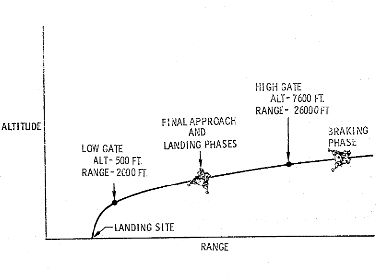
Apollo’s descent trajectory was composed of three phases: Braking, Approach, and Landing. Each phase existed to fulfill a specific goal or constraint: viewing the landing site to verify its suitability, respecting the engine thrust range, landing within the propellant margins, staying safe with a possible abort mode at all times, etc. Each phase performed a specific step during the descent:
- Braking: high efficiency horizontal velocity braking, spacecraft is close to horizontal (0-20 degrees). Full thrust during most of the phase, then throttling down to 0.50-0.60. Starts at 15 km and ends at High gate (2 500 m, -50 m/s).
- Approach: nulling horizontal velocity and reducing vertical velocity. Spacecraft is between 30 and 60 degrees with the engine throttled to 0.40-0.50. Ends when reaching Low gate (150 m, -10 m/s).
- Landing: vertical landing at 1 m/s, engine throttled to 0.30.
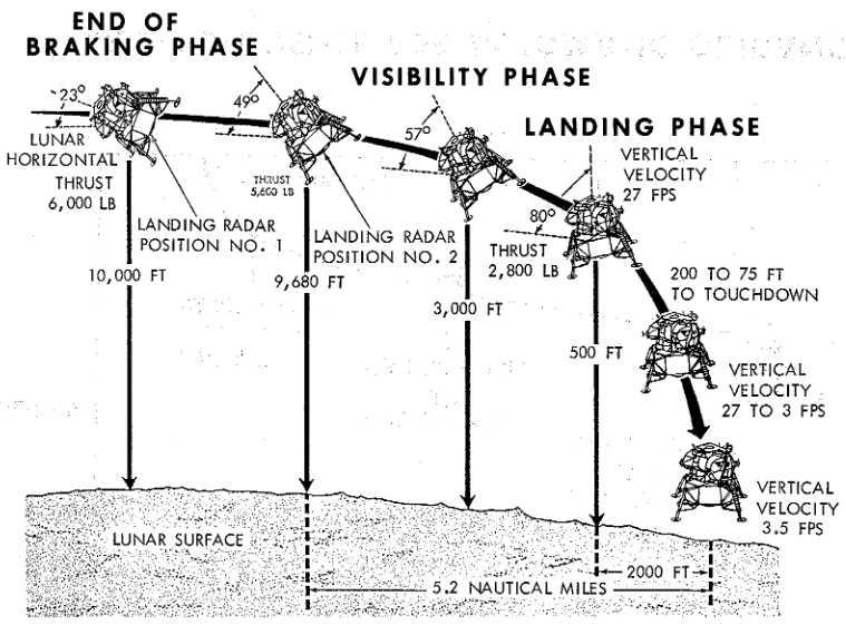
Apollo 11 Press kit, p44
Apollo 11 Press kit, p43
This strategy is great for many reasons, and even if some requirements will not matter as much (landing site redesignation, propellant margins, etc), I will use a similar trajectory. The High gate / Low gate pair is a good way to limit dispersion and reduce the risks.
Nonetheless, there will be two differences:
- Design the Low gate altitude to be lower than 150 m: no need to change the landing site.
- Faster landing with a more aggressive braking: final descent at 1 m/s is really slow and can be made faster.
Conclusion
GNC theory is easy and well known. Well, sure, it is rocket science and it is not so easy, but still, it is not too complicated.
The difficulty lies in modeling everything (for instance sloshing propellant) and designing a control law with sufficient control margins. With my knowledge of control theory and the help of papers about Apollo it should be feasible.
The quick and dirty prototype I made (full Python monolith, totally not like specified in this article) works surprisingly well: I made a control law similar to the one used by Apollo and it proved much more successful than I expected (Apollo landed on the Moon without issues after all). Of course there are still many things to adjust and clean, but it is a good start.
Stay tuned for the following articles!